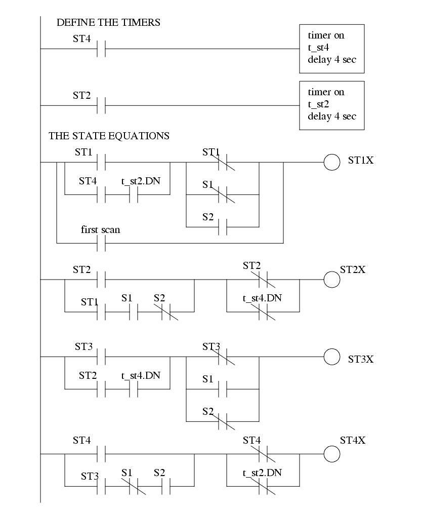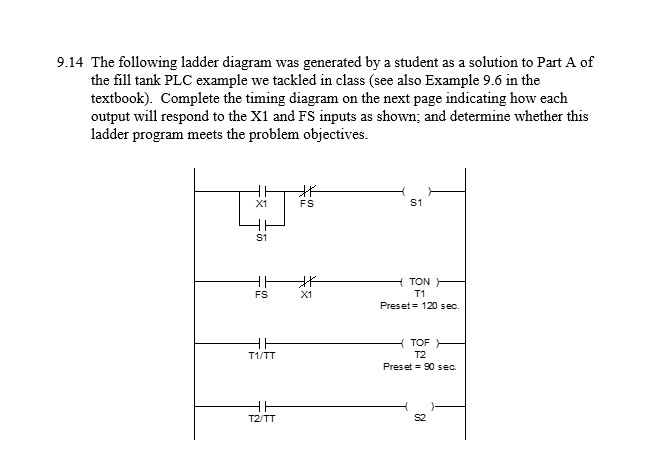

Normally-open contacts are empty within the space between the line segments, while normally-closed contacts have a diagonal line crossing through that space. The following computer screenshot shows a typical Ladder Diagram program being edited on a personal computer:Ĭontacts appear just as they would in an electrical relay logic diagram, as short vertical line segments separated by a horizontal space.

None of the contacts or coils seen in a Ladder Diagram PLC program are real rather, they act on bits in the PLC’s memory, the logical inter-relationships between those bits expressed in the form of a diagram resembling a circuit. Ladder diagrams are to be thought of as virtual circuits, where virtual “power” flows through virtual “contacts” (when closed) to energize virtual “relay coils” to perform logical functions. While Ladder Diagram programming has many shortcomings in its effort to remain more simplified, it remains extremely popular and so will be the primary focus of this chapter.Įvery Ladder Diagram program is arranged to resemble an electrical diagram, making this a graphical (rather than text-based) programming language. This language was invented for the express purpose of making PLC programming feel “natural” to electricians familiar with relay-based logic and control circuits. This is a graphical language showing the logical relationships between inputs and outputs as though they were contacts and coils in a hard-wired electromechanical relay circuit.

In the United States, the most common language used to program PLCs is Ladder Diagram (LD), also known as Relay Ladder Logic.


 0 kommentar(er)
